



Kimiya Yamaashi, Yukihiro Kawamata, Masayuki Tani, Hidekazu Matsumoto
Hitachi Research Laboratory, Hitachi, Ltd.
7-1-1 Omika, Hitachi, Ibaraki, 319-12 Japan
Phone: +81-294-52-5111
E-mail: yamaashi@hrl.hitachi.co.jp
Many applications, such as video conference systems,
remotely controlled systems and security systems, rely on
transmission of multiple video images through public
networks. For example, users of video conference systems
want to look at multiple video images showing all
participants in the conference at one time. Operators of
remotely controlled systems always look at multiple video
images of remote spots because problems may occur
anywhere. In these applications, each site is a long way
from the others. In video conference systems, sites may be
several hundred miles from each other. In remotely
controlled systems, remote spots may be several miles from
the control room. These systems need to use a public
network to transmit multiple video images because it is
very expensive to build a private network between such
remote locations.
Users are not interested in all the video images at a time.
They are watching a part of the video images carefully and
seeing the remaining video images peripherally to obtain a
global context of the situation. For example, when an
operator in a remotely controlled system is inspecting a
machine, the operator is carefully watching the video image
that shows the machine. The operator sees peripherally the
remaining video images only to grasp whether problems are
occurring there or not.
This paper describes a technique for transmitting multiple
video images, based on a user's interest, through a network.
The technique, User-Centered Video (UCV), compresses
video images of interest with high quality and degrades the
remaining video images according to the user's interest.
That is to say, the UCV assigns a larger part of a network
data rate to a video image of interest than the remaining
video images. The UCV transmits multiple video images
through the following steps:
There are several approaches to control display [4-6] or
image compression [7,8] according to a user's interest. For
example the Generalized Fisheye Views approach enables a
user to recognize a long program list by displaying the part
of interest in detail, while giving the whole list in a global
context [4]. These techniques control only screen space
among the computing resources. The UCV assigns network
data rates to multiple video images according to a user's
interest. The image query system developed by Hill et al.
[7] transmits a rough image of the whole image first and
then transmits a detailed image of the region specified by
the user. But, they discuss only transmission of a static
image. The UCV transmits multiple continuous media
(video images) through a network. Plompen et al. [8]
proposed a video conference system that tracks movement
of participants' heads. They assumed that participants in
one site are interested in the movement of participants'
heads in the other site. As they determined a user's interest
statically, the technique cannot adapt to dynamic changes
of the user's interest. The UCV evaluates the degree of the
user's interest dynamically so that it can adapt to the
dynamic changes.
In this paper, first we describe the concept of the UCV.
Then we describe the UCV in detail; the architecture,
evaluation of the degree of a user's interest, and
determination of video parameters (frame rate and number
of pixels). Finally we demonstrate the UCV with a
prototype system.
A typical application of the UCV is to a remotely
controlled system, such as a public water system shown in
FIGURE 1. The system locates several video cameras
around an intake tower to watch conditions (e.g., at the
floodgate for the intake, on the river, at gates to the water
channel, etc.). The system usually has several intake towers
that are several miles from the control room, so it is cost-
desirable to transmit multiple images around each intake
tower through a public network.
FIGURE 1
No caption given.
The MPEG technique allows only one video image at 30
frames/second through the ISDN-1500 network. So when
the system transmits 8 video images, MPEG transmits all
the video images at only 3-4 frames/second. It is hard for
an operator to control and watch the floodgate because
smooth motion of the floodgate is lacking with such a
degraded video image.
The system does not need to transmit the video images with
the same quality. During opening of a floodgate for intake
the operator is focusing on the video image of the floodgate
to examine the exact position and motion of the floodgate.
The operator needs to obtain the video image of the
floodgate with high quality. At the same time the operator
looks at global context of the remaining video images
rather than the details. For example, the operator is seeing
peripherally the video images of gates that are not being
handled. Because rough images of the gates allow the
operator to grasp whether the gates are still or not, the
operator does not need details such as the exact positions of
the gates.
The user's interest changes dynamically according to the
situation. For example, when some problems begin to occur
in a video image, the operator changes the user's interest to
the video image in which the trouble is occurring.
The UCV transmits video images of interest with high
quality by degrading the remaining video images, because
it is useless transmitting video images of little interest with
the same quality as video images of interest. The UCV
evaluates the degrees of the user's interest of video images
dynamically. The UCV assigns a network data rate to each
video image according to the evaluated degree of the user's
interest. The UCV changes quality of each video image to
fit them into the assigned data rate.
FIGURE 2
No caption given.
The UCV can also use a conventional video compression
technique (JPEG, MPEG and H.261) in the encode and
decode steps in FIGURE 2. The UCV compresses video
images more efficiently than conventional video
compression techniques.
FIGURE 3
No caption given.
In this paper the UCV formalizes DOI (Degree Of Interest)
of each video window as the following function:
DOI(x) = exp (-d)
where exp() is an exponential function and d is the distance
between a window x and the focused window. We define
DOI of the focused window as one (maximum). DOI of a
video window is equal to 0 when the distance from the
focused window is infinite.
In the UCV a user specifies the focused window explicitly
like an active window. There are many ways to detect the
focused window. For example an eye tracker can detect the
spot on which the user is focusing. We adopt a simple way
such as the user's explicit specification because most users
dislike wearing special devices such as glasses for an eye
tracker.
Determining video parameters of each video image
The UCV assigns a network data rate to each video image
according to the evaluated user's interest and determines
video parameters of each video image to fit it into the
assigned network data rate.
The UCV determines a network data rate in proportion to
the evaluated user's interest. The UCV calculates the
required network data rate to transmit each video image. If
the sum of the required network data rate is equal to or less
than the network bandwidth, the UCV assigns the required
network data rate to each video image. If the sum is greater
than the network bandwidth, the UCV divides the
bandwidth into the network data rates for video images in
proportion to the required network data rate multiplied by
the DOI of each video image.
The UCV determines the frame rate and the number of
pixels of each video image based on the assigned network
data rate. The data amount of a video image is expressed by
the mathematical product of the frame rate and the number
of pixels. The assigned network data rate determines only
the value of the mathematical product. The frame rate and
the number of pixels are traded-off. There are many ways
to determine the frame rate and the number of pixels. In
this paper the UCV calculates a temporary frame rate based
on the assigned network data rate assuming that the size of
each video image is equal to the displayed size of the video
image. The UCV then decreases the number of pixels by
decreasing the number of rows and columns sequentially
and it increases the frame rate until the frame rate becomes
more than the minimum frame rate that is specified in
advance.
There are regions of interest and regions of no interest in a
video image. For example, during opening of the floodgate,
an operator is carefully watching the region of the
floodgate, rather than the other places, such as the
background wall. The operator wants to look at the region
of the floodgate with higher quality even if the remaining
region is degraded.
In the UCV a user can create, delete and move a
rectangular region and change the resolution of the
specified region as shown in FIGURE 4. The UCV
transmits the specified region of interest with higher quality
by degrading the remaining region (the background
region).
FIGURE 4
No caption given.
The UCV changes the resolution of each region according
to the user's specified resolution of each region. The UCV
assigns the required network data rate to transmit each
region with the specified resolution, to the region from the
assigned network data rate. The UCV then degrades the
background region to fit it into the remaining data rate of
the assigned network data rate.
We might try to change the frame rate to change the data
amount of each region, but if the frame rates of regions are
changed, seams might appear at the edge of each region
because the digitizing time of each region is different. The
UCV does not change the frame rate of regions.
We assumed that the prototype system's bandwidth was 23
Mbits/second, which can display a video image (320
columns and 240 rows, 24 bits/pixels) at 13 frames/second.
The views of the system correspond to views of video
images transmitted with JPEG through ISDN-1500
networks, because JPEG can compress a video image at the
compression rate of 1.5-2.0 bits/pixel with
indistinguishable quality from the original [2].
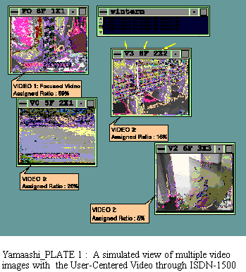
COLOR PLATE 1
COLOR PLATE 1.
YAMAASHI_PLATE 1 shows a view of 4 video images
(displayed size is 320 columns and 240 rows) with the
UCV. VIDEO SEGMENT 1 is the focused window designated FO. The
title bar of each video window shows the name and the
frame rate and the zoom rate of columns and rows. The
frame rate was adjusted to more than 5 frames/second in
determining the frame rate and the number of pixels. The
zoom rate is the rate of the displayed size and the digitized
size of a video image. For example, the zoom rate of a
column of 3 means that a digitized pixel is magnified to 3
pixels in the column direction when it is displayed.
Returning to our example, we see that an operator can
inspect details of a floodgate with smooth motion. Without
the UCV the operator can see all video images at only the
average frame rate (3 frames/second). This frame rate is too
low to observe effectively the motion of the floodgate. The
UCV can show the focused video image of the floodgate
with about three times smoother motion (8 frames/second).
The assigned ratio of the network bandwidth to the focused
video images is 59 %.
DYNAMIC FIGURE 1:
No caption given. (QuickTime Movie, about 10 mb)
The UCV degrades the remaining video images according
to the distance from the focused video image. For example
VIDEO SEGMENT 3 is displayed with the zoom rate of 2x2 at 8
frames/second. The assigned ratio of the network
bandwidth for VIDEO SEGMENT 3 is 16 %. VIDEO SEGMENT 2, which is the
farthest from the focused window, is displayed with the
zoom rate of 3x3 at 6 frames/second. The assigned ratio of
the network bandwidth for VIDEO SEGMENT 2 is only 5 %.
The operator can obtain the global motion of video images
even when they are degraded. For example, VIDEO SEGMENT 2
shows carp in the water quality monitoring tank. The
abnormal motion of the carp means that the water is
polluted with something. The operator needs to examine
the carp motion to grasp whether the water quality is
normal or not. VIDEO SEGMENT 2 does not show the carp in detail
(e.g., the pattern of carp's bodies), but the global context
which allows the operator to judge whether the carp are
swimming normally or not.
This example shows that the UCV allows an operator to
obtain a smoother video image of interest with a global
context of video images.
COLOR PLATE 2
COLOR PLATE 2
YAMAASHI_PLATE 2 sho.ws a view of video images with
the UCV. YAMAASHI_PLATE 3 shows a magnified
image of the focused video image. An operator can
understand the global motion of each video image, but the
network bandwidth is too low to examine the focused video
image in detail. The zooming rate of the focused video
image is 3x3. The operator can not read the water level
with the numbers on the water gauge to inspect the water
level.
COLOR PLATE 3
COLOR PLATE 3.
In YAMAASHI_PLATE 3 the operator specifies a region
of the water gauge as a region of interest, then the UCV
shows the video image of YAMAASHI_PLATE 4. The
specified region of interest is shown with the red rectangle.
The UCV shows the region of interest (80 columns and 45
rows) at full resolution (zooming rate 1x1), while the
resolution of the background is 1.8 times rougher than
YAMAASHI_PLATE 3. In YAMAASHI_PLATE 4 the
operator can read the numbers on the water gauge.
This example shows that the UCV allows an operator to
look at numbers on a gauge by specifying the region as a
region of interest, while the numbers cannot be seen
without the UCV.
COLOR PLATE 4
COLOR PLATE 4.
We demonstrated the UCV using examples that simulated
views of multiple video images with ISDN-1500 and
ISDN-64 networks. The example for the ISDN-1500
network demonstrated that the UCV allows a user to get the
focused video with much smoother motion than without the
UCV and the global context of video images is obtained
even while the remaining video images are degraded. The
example for the ISDN-64 network illustrated that the UCV
allows a user to look at the details of regions of interest by
degrading the remaining regions, although the user cannot
look at the details without the UCV.
We assigned network data rates to video images according
to the user's interest. In the future, we would like to assign
computing resources also according to user's interest. For
example, graphic power of three dimensional (3D) graphic
hardware is a limited computing resource. When a user
displays multiple 3D graphics, the required graphic power
overwhelms the power of the graphic hardware. It is
desirable to assign the graphic power according to the
user's interest.
Abstract
Many applications, such as video conference systems and
remotely controlled systems, need to transmit multiple
video images through narrow band networks. However,
high quality transmission of the video images is not
possible within the network bandwidth.
This paper describes a technique, User-Centered Video
(UCV), which transmits multiple video images through a
network by changing quality of the video images based on
a user's interest. The UCV assigns a network data rate to
each video image in proportion to the user's interest. The
UCV transmits video images of interest with high quality,
while degrading the remaining video images. The video
images are degraded in the space and time domains (e.g.,
spatial resolution, frame rate) to fit them into the assigned
data rates. The UCV evaluates the degree of the user's
interest based on the window layouts. The user thereby
obtains both the video images of interest, in detail, and the
global context of video images, even through a narrow
band network.
Keywords:
Networks or communication, Digital video,
Compression, User's interest, Computing resources
Introduction
Most image compression techniques, such as H.261 [1],
JPEG (Joint Photographic Experts Group) [2] and MPEG
(Moving Pictures Experts Group) [3], are not user-centered.
These techniques compress a video image in the same way
without considering what a user is watching in the video
image. Furthermore they cannot allow transmission of
multiple video images through a narrow band network such
as a public network like ISDN (Integrated Services Digital
Network). For example, the MPEG technique allows only
one video image to be transmitted through the ISDN-1500
(1.5 Mbits/second) network [3]. Since the technique
degrades all the video images uniformly to fit them into the
network, a user cannot obtain video images of individual
desired quality.
CONCEPT OF USER-CENTERED VIDEO
USER-CENTERED VIDEO
Architecture of UCV
A schematic diagram of the UCV is shown in FIGURE 2.
Only the receiver gets the user's conditions. In the UCV the
transmitter not only sends video images to the receiver, but
also receives information about the user's interest from the
receiver. The UCV adds two steps to the conventional
video transmitting steps: (1) dynamic evaluation of the
degree of the user's interest; and (2) determination of video
parameters (frame rate and number of pixels of each video
image) of each video image.
Evaluating user's interest
The UCV evaluates a user's interest based on window
layouts. For example, when a user compares two video
windows, the user locates these video windows close to
each other to look at both at one glance. We can estimate
the user's interest based on the distance between windows.
The degree of a user's interest decreases with the distance
from a focused window as shown in FIGURE 3. When the
user is focusing on a region, user's visions are clear at the
center of the view and fuzzy in the surrounding regions.
This is because the retina of a human eye is hierarchically
decomposed into a foveal region that perceives details and
a surrounding low resolution region [5].
UCV IN A VIDEO IMAGE
Specification of a region of interest
The UCV transmits a video image of interest with higher
quality than without the UCV. When a user wants to look at
the video image of interest with higher quality, the UCV
allows the user to obtain the regions of interest in the video
image with higher quality by degrading the remaining
region.
Video parameters of each region
EXAMPLES WITH A PROTOTYPE SYSTEM
Example for ISDN-1500
We developed a prototype system that simulates views of
video images transmitted by the UCV. The system digitizes
and displays multiple video images while changing the
frame rate and the number of pixels of each video image so
that the total data amount of the video images is equal to
the assumed bandwidth. This prototype system can
simulate views of video images through any network by
changing the bandwidth.
Example for ISDN-64
We simulated a video transmission with the ISDN-64
network. We assumed the bandwidth of the prototype
system was 1.9 Mbits/second, which can transmit a video
image (320 columns and 240 rows, 24 bits/pixels) at 1.1
frames/second. The ISDN-64 network has 2 data lines (64
Kbits/second) and 1 control line (16 Kbits/second). We can
use 2 data lines to transmit video images. The network
bandwidth is 128 Kbits/second. The views of this prototype
system correspond to views of video images with JPEG
through the ISDN-64 network.
CONCLUSION
We have proposed a User-Centered Video (UCV) that
transmits multiple video images with a narrow band
network. The UCV assigns network data rates to video
images and regions of a video image according to the user's
interest. The UCV evaluates the degree of the user's interest
from window layouts (distance from the focused window)
and direct specification of regions of interest in a video
image.