

Wayne Citrin, Jeffrey D. McWhirter
There has been very little work on the problems of
manipulating diagrams in a graphical editor, and particularly
in defining diagram entry mechanisms' behavior in an
intelligent way. For example, consider a generic graphical
editor used for the construction of trees. When an object or a
group of objects are added into a diagram, they are simply
inserted into the diagram area and perhaps overlaid on
already-existing elements. In neither case are repairs made to
maintain the integrity of the tree. Thus, entering nodes may
require a substantial number of additional insertions and
deletions to bring the tree to the desired structure. This
problem generalizes to many types of structured diagrams.
We are interested in exploring user interaction mechanisms
in graphical environments [1] . In this effort we are currently
investigating ways to facilitate the entry and construction of
diagrams. The underlying idea of this effort is rather simple:
relations (edges, for example) are automatically added
between elements in a graph based on the element type and
the initial spatial relationship of the elements. Elements
may also be merged into existing relationships. A
fundamental aspect of our work is that the target
environments we address are not simply graphical editors,
but rather are visual language environments. The constructs
that are created and manipulated by the user are language
constructs, not simply graphical shapes. This perspective
lets us take advantage of the underlying syntax and
semantics of the visual language to govern the editing
behavior. With knowledge of the syntax, semantics, and
drawing style of the visual language, it should be possible
to automate the steps in which edges are added and removed.
We have implemented intelligent entry mechanisms in a
variety of environments, including simple flowchart and tree
editors, interactive table editors, and a prototype music
editor.
Using the Escalante system for specifying and generating
graphical environments [2] , we have implemented a set of
prototype environments for exploring issues related to
diagram entry.
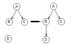
Figure 1 is a snapshot from a simple tree editor. In the
figure, node D is added to the graph. This causes the
addition of an edge between nodes B and D due to the spatial
relationship between the nodes. The specific entry rule used
states that when a new node is under another node, and the
new node does not already have any input edges, then an
edge is added between the two nodes.
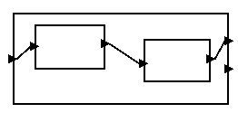
Figure 2 shows an example visual language that consists of
a set of component (square) and port (triangle) elements.
Two different diagram entry behaviors are defined. The first
causes the addition of a semantic relation (not shown)
between two components when one is spatially contained
by another. The second causes the addition of a semantic
relation between a port and the nearest component. Note
that the underlying relations, once added, are active and
operate to enforce diagram syntax and semantics during
subsequent manipulations.
FIGURE 2: Nesting and port example.
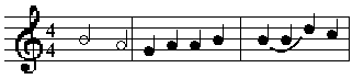
FIGURE 3: Music notation example.
In defining entry behavior, one is not limited to basic
node/edge representations. Figure 3 shows a prototype
music notation editor, the basic elements of which are clefs,
staffs, and notes. Rules have been defined that cause the
addition of underlying semantic relations among elements.
For example, when a staff element is added, a relation is
automatically added between the nearest clef and the newly
added staff. Likewise, when a node is added, it is connected
to the nearest staff.
Figure 4 gives an example of cut and paste in a flowchart
editor. In this case, the paste operation is treated as an entry
operation. We assume that the flowchart in figure 4(a) is to
be transformed so that the decision node comes after node E.
We cut the decision node, resulting in the flowchart of
figure 4(b). The decision node has been copied to the
clipboard, preserving in the clipboard the connections
between the cut decision node and the remaining diagram.
When we paste the decision node back into the flowchart
(figure 4(c)), the connection between the node and statement
C is restored, and an edge from E to the decision node is
automatically constructed, as is a connection from node D
to node F, since the node below the decision node is
assumed to be a join node. Entry behavior works in this
way because the entry rule that indicates that an inserted
node be connected to a node immediately above is assigned a
higher priority than the entry rule that states that preserved
connections in the clipboard be re-established.
FIGURE 5: Entry specification.
The Escalante environment provides the means to specify
some basic diagram entry operations. Figure 5 shows a
partial specification of the entry behavior of the tree
example. One can declaratively define the automatic addition
of relations between elements based on a certain set of
criteria including element type, initial spatial position,
nearness, etc. The specification in the figure states that
when a new element of type Node is under an old element of
type Node then add an Edge from the old element to the new
element if the new element does not already have an input
Edge. The flowchart behavior was defined using both the
Escalante specification facilities in concert with manual
programming. The manual programming that was required
saved the previous context of the subgraph when it was cut
and reconnected the pasted subgraph into the new context.
Rules based on the semantics of a language and the initial
spatial relationships of the language elements are simple to
define and implement yet powerful in their ability to
facilitate diagram entry tasks. We have demonstrated this by
constructing a set of simple purpose-built editors. We are
currently investigating general diagram entry rules and plan
to implement editors that exhibit more complex interaction
behavior.
Abstract
Although great strides have been made in the last 10-15
years in the development of systems that use graphical
representations, very little work has been done in
developing systems that help users input and edit diagrams
efficiently. This paper describes an ongoing project
addressing the design of one such feature of a graphical
editor: diagram entry. We show how knowledge of the
syntax and semantics of the language being edited allows us
to design a more intelligent diagram entry facility.
Keywords
Graphical editors, visual languages, diagram entry.
Introduction
OUR APPROACH
EXAMPLES
Tree Editor
Nesting and Port Example
Music Notation
Flowchart Example
DEFINING DIAGRAM ENTRY BEHAVIOR
CONCLUSION